The Sentinel in the Storm: How a WiFi-Connected Nano ESP32 Monitors the Sky
By FJ Snijman - He writes about divorce, electronics, passive income, ZX14R, local SEO and small businesses
October 20, 2025
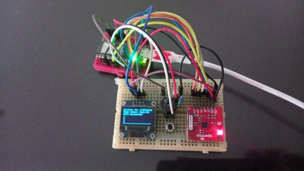
We've all experienced the sudden, unnerving silence before a summer storm breaks. But what if you had a silent digital sentinel constantly scanning the horizon, ready to alert you and log every strike to the cloud? Welcome to the world of the Lightning Detector with WiFi - Nano ESP32, a project defined by its powerful AS3935 sensor integration and robust web connectivity.
This isn't just a simple sensor hookup; it's a dedicated piece of firmware designed to provide real-time lightning detection, track storm history, and communicate critical data to a remote server.
Chapter 1: The Initialization – Awakening the Sentinel
Every successful mission starts with preparation. Our sentinel begins its life by initializing its communication channels, starting the serial connection, and connecting to the user's WiFi network.
The code defines its digital identity and destination:
// ------------------------
// WiFi Configuration
// ------------------------
const char* ssid = "....."; // Replace with your WiFi SSID
const char* password = "....."; // Replace with your WiFi password
const char* serverUrl = "https://sparksky.vercel.app......"; // Replace with your Vercel domain
The device uses these credentials to initiate its connection. Once connected, it logs its IP address and uses the server URL to dispatch its observations. Crucially, the system is designed to check the WiFi connection every 10 seconds (wifiCheckInterval = 10000) and attempt reconnection if necessary, ensuring continuous operation.
Next, the specialized AS3935 sensor is brought online. This sensor uses configuration parameters such as noiseFloor, watchDogVal, and lightningThresh. The device is initially configured for OUTDOOR operation.
Chapter 2: The Watch – Detecting the Event
The core mission runs inside loop(), constantly monitoring for interrupts from the AS3935. The interrupt pin (lightningInt) signals events. The sensor can raise one of three events:
- Noise (NOISE_INT): caused by electrical interference; a noise event is sent to the server.
- Disturber (DISTURBER_INT): a non-lightning electrical event.
- Lightning Strike (LIGHTNING_INT): the main event that triggers logging and alerts.
When a lightning strike is detected, the sentinel leaps into action:
else if(intVal == LIGHTNING_INT) {
    Serial.println("Lightning Strike Detected!");
    if(beepEnabled) {
        soundBuzzer();
    }
    lightningCount++;
    byte distance = lightning.distanceToStorm();
    // ... data logging and display functions follow
}
If the buzzer (beepEnabled) is on, it plays a tone at 2500 Hz for 1000 ms. The AS3935 reports the storm distance in kilometers.
Chapter 3: Data Dispatch and Visual Alert
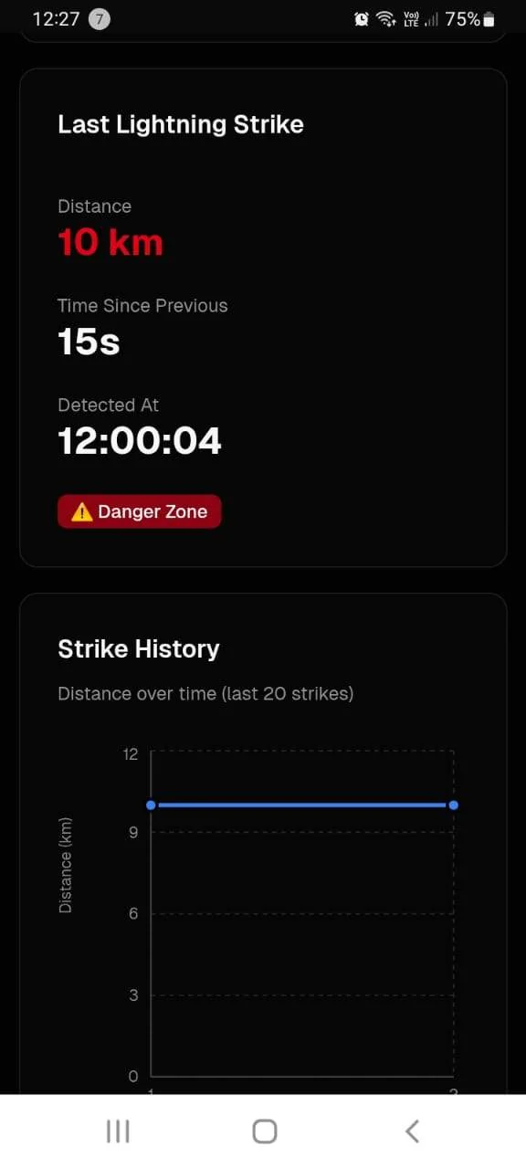
The measured distance is pushed into a history array that holds the last 20 strikes (MAX_STRIKES = 20). Then the device prepares a JSON payload and sends it to the server with up to three retries (MAX_RETRIES = 3).
String jsonData = "{";
jsonData += "\"type\":\"lightning\",";
jsonData += "\"distance\":" + String(distance) + ",";
jsonData += "\"count\":" + String(lightningCount) + ",";
jsonData += "\"timeSinceLastStrike\":" + String(timeSinceLastStrike) + ",";
jsonData += "\"mode\":\"" + String(isOutdoorMode ? "outdoor" : "indoor") + "\",";
jsonData += "\"buzzerEnabled\":" + String(beepEnabled ? "true" : "false");
jsonData += "}";
While the server receives the event data, the device also updates its RGB LED and OLED display. The RGB LED uses color codes to reflect storm proximity:
- Close Storm (≤ 10 km): Red LED.
- Mid-range Storm (≤ 40 km): Yellow/Amber LED.
- Distant Storm (> 40 km): Green LED.
The OLED displays: event count, measured distance, time since last strike, and a small history graph of recent strikes.
Key takeaways
Quick summary of what matters: detection, logging, and remote visibility.
Chapter 4: Adaptation and Control
Users change operation using modeTogglePin. A short press toggles Outdoor and Indoor modes. A long press (>1000 ms) toggles the buzzer state. After each manual change the device sends a sendStatusUpdate() to the server.
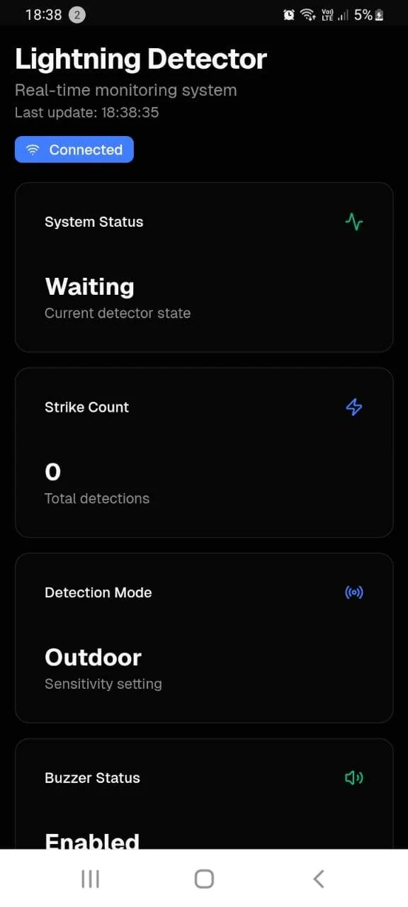
The detector polls the server for settings updates every 5 seconds (settingsCheckInterval). The web app can switch modes remotely, enabling dynamic, remote control when the device is far away.
By combining sensor hardware, networking, and simple physical controls, this firmware yields a vigilant, cloud-connected instrument dedicated to watching volatile skies.
Video: https://youtu.be/nJbQebNeDtg
Takeaways
- Keep WiFi credentials secure. Use secure server endpoints (HTTPS).
- Tune AS3935 parameters for local noise conditions to reduce false positives.
- Use retries and local buffering to avoid losing strike data during short outages.
- Make the device resilient: watchdog timers, periodic health checks, and OTA updates if possible.

Written by FJ Snijman
Hardware Architect • Chemcool Electronics
Senior embedded systems designer and author at Chemcool Electronics in Centurion, South Africa. Specializing in AVR microcontrollers, ESP32 IoT nodes, and solar battery storage management.